Tip
Floor mapping is designed for transferring image from camera to the floor surface. It is required for TRASSIR showing people movement on the map, detected by Neuro detector. It is also required for building heatmap.
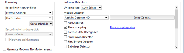
To activate the plugin go to Channel settings to the Software detectors settings area and select Floor mapping. Click Setup floor mapping link to open the settings window.
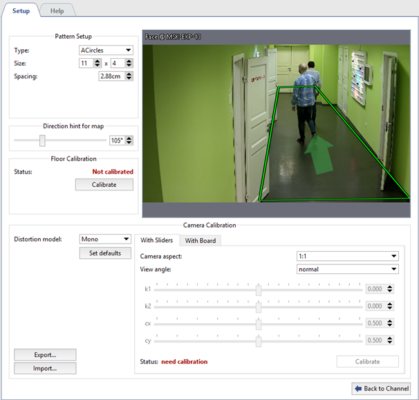
Th detector settings window will open:
Important
The module is configured by calibration with the help of a special template.
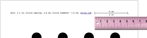
Before starting a calibration, download a template from the website nerian.com. Print it in 1:1 scale in A2 format or bigger sheet.
Check the scale of the received template using the ruler.
Settings
-
Make the module preset
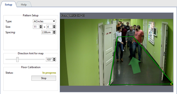
In the Pattern Setup group of settings enter the parameters of the template to perform calibration. All required parameters are specified in the template.
- Type - the type of the template.
- Size - number of lines and rows.
- Spacing - the distance between the template items.
-
Floor calibration
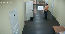
Before starting the calibration, put template on the floor in such a way to ensure its coming into image coverage in full . Click Calibrate in Floor calibration settings group and wait for the calibration completion. Calibration is deemed to be completed when the value in Statuschanges to Calibrated.
Tip
Floor calibration is not required in case of using Fisheyecameras.
Important
Floor re-calibration is required in case of the change of:
- camera installation location;
- camera tilting angle;
- focal distance of the lens.
-
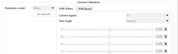
Camera calibration
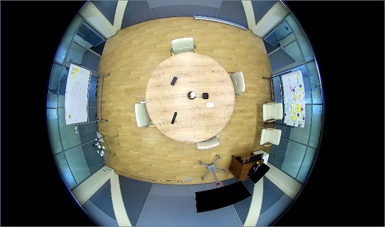
To start with select the Distortion model installed on the camera: Mono or Fisheye.
Further calibration of camera can be done in two ways:
-
With sliders
On the "With sliders" tab in Camera aspect and View angle fields select height-to-width aspect of maximum resolution and lens vision's horizontal angle.
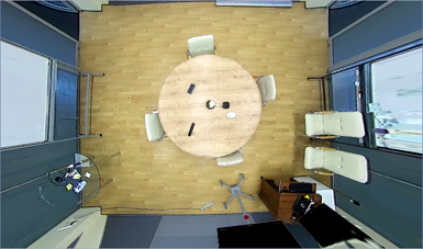
Then on click Calibrate and changing the sliders adjust the image deterioration in such a way to make all straight lines in real life (walls and floor borders, door and window reveals, etc.) straight in the image. On completion click on Stop.
-
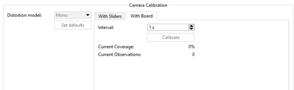
Camera calibration with board
On the With board tab in Interval field enter the time which will pass between neighboring calibrations.
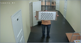
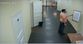
Further on calibration shall be done as follows: one person shows a template to the camera in various points of the shooting area and the other person clicks Calibrate and monitors the changes in the values of Current Coverage and Current Observations.
The calibration is considered to be completed when the Current coverage parameters will exceed 80%. Click Stop,to stop calibration and fix the result.
Tip
Set defaults resets the camera calibration settings.
The camera calibration depends on the camera model and lens installed on it. Thus making single camera calibration you can conduct Export / Import of settings to the other camera of the same model and with the same lens.
-
-
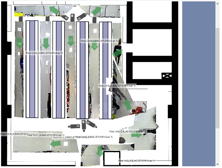
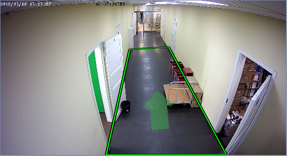
Floor area marking
Modify the position of the rectangle points in such a way to make the marked area to enframe all visible surface of the floor. If necessary, add the desired number of points using the context menu.
Further on to ensure the correct floor area location on the map you'll need to orient it in space. To do this using Direction hint for map direct an arrow in such a way to direct it on the one of the walls or make parallel to the passage.
-
Calibration validity check
Calibration validity test can be done by adding floor area on the map. Under correct settings floor area will be maximum approximated to the plan.